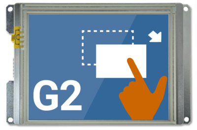
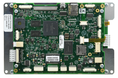
5.7″ G2H2 Resistive
Part Number: 51-0406-081
G2H2 Controller
- CPU: NXP i.MX 6Solo, 1.0 GHz Processor including hardware video decoder and 3D graphics engine.
- Storage Capacity: 512 MB DDR3 DRAM. 512 MB NAND Flash / 16 MB NOR Flash. microSD Flash Card Socket.
- I/O Interface: 10/100/1000 Mbps Base-T Ethernet: Features low profile Molex Pico-SPOX Connector (24 AWG Compatible). One RS-232 and one 3.3V CMOS Serial Port. One RS-485. One USB 2.0 (High Speed) Host Port. One USB 2.0 (High Speed) On-The-Go (OTG) Host Port. One I2C Port. One CAN Bus with Transceiver. 8-bit GPIO Port 5V Tolerant.
- Audio: Codec with 1 Watt Audio Amplifier and Speaker
LCD Display
- Display Type: 5.7″ Diagonal TFT Color LCD
- Resolution: 640 x 480 VGA, 18-bit Color
- Orientation: Landscape
- Luminance (with touch): Typical 620 (cd/m²)
- Viewing Angles: 65/65 left/right, 60/70 up/down
- Backlight: LED
- Manufacturer: Evervision
Get detailed panel specifications.
Touchscreen
- Type: 4-Wire Analog Resistive
- Touch Driver: Standard Linux Driver
- Durability: Over One Million Touches
Dimensions
6.325” W x 4.118” H x 1.054” D
Environmental/Regulatory
- Operating Temperature: 0 to 70° C; Contact us for extended temperature.
- Storage Temperature: -30 to 80° C
- Humidity: Max 90%RH at 60° C; No Condensation
- RoHS 2 Compliant: Yes
Power Requirements
- Power Supply Voltage: +5VDC (5.15V for 5V USB Host Port Power Out)
- Power Consumption: Max 970mA during boot with no devices attached.
Grounding
The G2H2 module requires a 5V DC input, +/- 5%. At boot-up, it uses a maximum of 970 mA with no external devices attached. If the module is supplying power to external USB devices (500mA max.), the input power should be a minimum of 5.15 V to meet the USB specification at the far end of the longest USB cable run. The module can also supply +5V to other external devices on some of the connectors, and all such supplies need to be considered in the power budget. The input power connector can handle 3A of nominal 5V input.
The board mounting holes are connected to digital ground. These must be connected to chassis ground either directly or through a transient protection diode for ESD.
Mounting Options
For 5.7″ modules, Reach Technology provides gaskets. Visit Mounting Options for more information.
Software Releases
Download a new software release by selecting the appropriate model and kernel image from the table below (usually the latest version). Then visit the SD Card section for a discussion on tools you can use to install the new software on your SD card.
See how to get your development kit set up, learn more about QML development, see Application Notes, and more resources to get started in G2H v1.8 Software Documentation.
This video shows you how to get your kit up-and-running once it arrives.
See how to set up an application, design your first screen, and download code to the module. These videos were created using a 7″ display module yet apply to this 5.7″ module.
See how to set up an application, design your first screen, and download code to the module. (Note: Instead of using 800 x 600 to define the rectangle dimension of a 7″ screen as shown at 1:16 minutes into the video, change “Rectangle Width” to “640” and “Rectangle Height” to “480” for the 5.7″ screen).
Find more tutorial resources.
Embedded Touchscreens Made Easy:
Up in Days, Smoothly to Production. Get started with a Development Kit.
Reach Technology is now a part of Novanta.
Sales and Engineering
545 First Street
Lake Oswego, OR 97034
503-675-6464
sales@reachtech.com
techsupport@reachtech.com
Manufacturing
4600 Campus Place
Mukilteo, WA 98275
service@reachtech.com
Please send payments to:
Novanta Corporation
PO Box 15905
Chicago, IL 60693
accounts.receivable
@novanta.com


