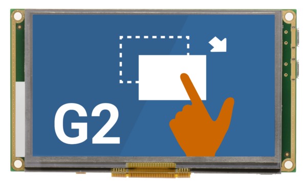
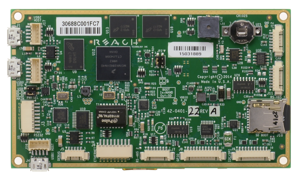
4.3″ G2C1 Projected Capacitive
Part Number: 51-0401-34
G2C1 Controller
- CPU: NXP i.MX28 454Mhz Processor
- Storage Capacity:
- 128 MB DDR2 DRAM Onboard
- 256 MB NAND Flash Onboard
- I/O Interface:
- 10/100 Mbps Base-T Ethernet: Features low profile Molex Pico-SPOX (24AWG Compatible Crimps) and MAC / PHY Onboard
- RS-232, RS-422/RS-485 (2), 3.3V CMOS Serial Ports
- Two USB 2.0 (High Speed) Host Ports
- One USB 2.0 (High Speed) On-The-Go (OTG) Port
- One I2C Port
- One CAN Port
- 8-bit GPIO Port 5V Tolerant
- Contact us for additional I/O options.
- Audio: Beeper
Software Features
- Linux Kernel 2.6.35 with Qt 4.8.4 and QtCreator IDE 2.8.0
- Samba File Server for easy file access from Windows
- UBIFS NAND Flash file system for speed and reliability
- USB Hotplug for module Host Ports
- SSH Server
- Ships with Serial Interface for QML Applications. See Application Notes to convert to Ethernet or CAN connection.
- Custom Linux Kernel Build Supported and Maintained by Reach Technology. Contact us for your specific requirements.
LCD Display
- Display Type: 4.3” Diagonal TFT Color LCD
- Resolution: 480 x 272 WQVGA, 24-bit Color
- Orientation: Landscape, Portrait, 180° Flip
- Luminance (with touch): Typical 400 (cd/m²)
- Viewing Angles: 70/70 left/right, 50/70 up/down
- Backlight: LED
- Manufacturer: FEMA Electronics
Get detailed panel specifications.
Touchscreen
- Type: Glass/Glass
- Controller: Included
- Cover (Décor) Glass: Optional; Contact Reach
- Multi-touch: Hardware Supported; Software Contact Reach
Dimensions
4.65″ W x 2.65″ H x .522″ D
Environmental/Regulatory
- Operating Temperature: -20 to 70° C; the LCD temperature range primarily limits this
- Storage Temperature: -30 to 80° C
- Humidity: Max 90%RH at 60° C; No Condensation
- EMI and ESD Test Results Available: Contact Reach
- EMI and ESD Test Results Available. See EMC Testing Results and ESD Testing Results.
- Passes FCC Class B Emissions without an enclosure (8-layer fully shielded PCB)
- Survives 27KV ESD (in an enclosure) to pass strict gaming commission standards
- Thermal, Mechanical, Vibration: Contact Reach
- RoHS 2 Compliant: Yes
Power Requirements
- Power Supply Voltage: +5VDC (5.15V for 5V USB Host Port Power Out)
- Power Consumption: Max 650mA/5VDC
Grounding
The G2C1 module requires a 5V DC input, +/- 5%, on jumper J3. At boot-up, it uses a maximum of 650 mA with no external devices attached. If the module is supplying power to external USB devices (500mA max.), the input power should be a minimum of 5.15 V to meet the USB specification at the far end of the longest USB cable run. The module can also supply +5V to other external devices on some of the connectors, and all such supplies need to be considered in the power budget. The input power connector can handle 3A of nominal 5V input. The module can also be powered via the USB OTG connector. Please consult Reach Technology for requirements to power this way.
The board mounting holes are connected to a digital ground. These must be connected to a chassis ground either directly or through a transient protection diode for ESD. The resistive touch circuit has ESD protection that shorts ESD on the touch panel to the board mounting holes.
Mounting Options
Gaskets are available, visit Mounting Options for more information.
Software Releases
Download a new software release by selecting the appropriate model and kernel image from the table below (usually the latest version). Then visit the SD Card section for a discussion on tools you can use to install the new software on your SD card.
Documentation
See how to get your development kit set up, learn more about QML development, see Application Notes, and more resources to get started in G2C v1.0 Software Documentation.
Tutorial Videos
Watch how to get a 4.3″ kit up and running once it arrives.
See how to set up an application, design your first screen, and download code to the module.
Find more tutorial resources.
Accessories
Consider getting a microSD card extension cable if you are doing a lot of development and frequently replacing the microSD card in your module.
Other accessories come with Development Kits. However, some customers need additional items for prototyping. In that case, items can be purchased online by model.
Embedded Touchscreens Made Easy:
Up in Days, Smoothly to Production. Get started with a Development Kit.
Reach Technology is now a part of Novanta.
Sales and Engineering
545 First Street
Lake Oswego, OR 97034
503-675-6464
sales@reachtech.com
techsupport@reachtech.com
Manufacturing
4600 Campus Place
Mukilteo, WA 98275
service@reachtech.com
Please send payments to:
Novanta Corporation
PO Box 15905
Chicago, IL 60693
accounts.receivable
@novanta.com


